PRODUCTION ENGINEERING II
PART-A
9 X 1 = 9 Marks
Answer all questions in one word or one sentence. Each question carries one mark
1. Mention the use of knurling
The purposes of knurling are:
1. To provide an effective gripping surface
2. To provide better appearance to the work
3. To slightly increase the diameter of the work
2. List the machines on which drilling can be done
Drilling Machine, Milling Machine, Lathe
3. How does quick return mechanism help ?
Quick return mechanism help to reciprocate the ram of the shaper
4. Mention the use of clapper box
Clapper block holding the cutting tool lift in the return stroke of the ram and avoid rubbing of the back edge of the cutting tool
5. Which part of the planer machine moves while machining a workpiece?
Table
6. How does gang milling differ from the normal milling operation ?
In gang milling, a number of milling cutters are fitted together on the spindle to mill the required shape in the workpiece. But in normal milling, only one type of cutter is used to mill the workpiece.
7. Mention any two ways of making a gear
Gear Milling, Gear Hobbing
8. Define the term grit in the grinding wheel
The grinding wheel is made up of thousands of abrasive grains. The grain size or grit number indicates the size of the abrasive grains used in making a wheel
9. Why should truing be done on a grinding wheel
Truing is done on the grinding wheel to make its outer periphery concentric to the axis of rotation
PART-B
Answer any 8 questions from the following. Each question carries three marks
8 x 3 = 24 Marks
1. List down the specification of a lathe
Lathe is specified by the following dimensions:
1. The height of the centre measured from the lathe bed
2. The swing diameter over the bed
3. The length between the centres . This is the maximum
length of the work that can be turned between centres
4. The swing diameter over the carriage
5. The maximum bar diameter .This is maximum diameter of the bar stock that will pass through the hole of the headstock spindle
6. The length of the bed
2. List down the operations using a shaper
The various machining operations that can be performed with shaper are:
1. Horizontal surface machining
2. Vertical surface machining
3. Angular surface machining
4. Irregular surface machining
5. Cutting slots, grooves and key ways
6. Cutting gears and splines
3. List down the differences between a shaper and planer
Shaper
- The ram holding the tool reciprocate and the table holding the work piece is fixed
- Feed can be given to the work piece or tool
- Intended for small jobs
- Only single tool can be used at a time
Planer
- The table holding the work piece reciprocate and the ram holding the tool is fixed
- Feed can be given to the tool only
- Capable of holding big and heavy jobs
- Multiple tools can be used to machine more than one surface together
4. Sketch the parts of a slotter
5. Mention the working principle of a shaper
In a shaper, the speed of the backward stroke (idle stroke) of the ram is more than the forward stroke. The principle of this quick return is explained with the figure.
The forward cutting stroke take place when the bull gear rotate through the angle C1KC2 and return stroke on C2LC1.It is evident that the angle made by the return stroke is smaller than that of the forward stroke. So the return stroke complete in a short period of time than that of forward stroke.
6. Mention the process of machining in conventional milling
In conventional milling or up milling, a cutting tool called milling cutter is rotated and the work piece is fed against the direction of rotation of the cutter. The material is removed in the form of chips. The operation is performed in milling machine. Milling machine may be Horizontal or vertical type.
In Horizontal milling machine milling cutter is mounted on a horizontal arbor attached to the spindle and is rotated. The work piece is fixed on the table by using work holding devices like t-nut and bolts, milling vice, v-block etc. depend on the type of work piece. The figure illustrate the process of conventional milling.
7. Briefly explain any two milling methods
1. Face
milling
In face milling the cutter axis is perpendicular
to the surface to be generated. Actually the face does not cut as the name
indicates. But the peripheral cutting edges remove the material primarily and
the face cutting edges act as secondary cutting edges.
1. End
milling
End milling is an operation of
producing narrow slots, grooves, ways and vertical flat surfaces on the work pieces
by using end mills. End milling can be performed horizontally, vertically or at
an angle in reference to the table.
The figure illustrates the Face milling and End milling processes.
8. Briefly explain the process lapping
Lapping is performed
by using lap and abrasive powder. Abrasive powders like emery, corundum,
aluminium oxide etc. are rubbed against the surfaces of job with the help of a
lap made of soft materials like brass, copper, lead, soft cast iron, soft steel
etc. Lapping is performed manually or by machine. The figure illustrates the
method of lapping the face of small blocks in a vertical axis lapping machine.
Lapping remove very
thin layer of metal (0.005 to 0.1mm).It is performed to correct minor surface
imperfections, improve dimensional accuracy or to maintain fit between two
mating parts. It is considered as a low efficiency process in surface finishing
operations.
9. Briefly explain the process of gear hobbing
Hobbing uses a helically fluted cutting tool called a hob. Both the hob and the
work piece rotate as the hob is fed axially across the gear blank. Hobbing is
limited to producing external gear teeth on spur and helical gears. Hobbing can
be performed on a single gear blank, but also allows for stacking of multiple
work pieces, increasing production rates. The figure illustrate the gear hobbing process.
1. Gear Hob 2. Gear blank
10. Why is dressing an important aspect in grinding wheel ?
Removing the abrasive grains from the face of the grinding wheel to
sharpen the wheel is called dressing. Dressing is carried out by a single point
diamond tool in precision grinding machines. A star dresser is used in pedestal
grinder for wheel dressing.
The objective of dressing the wheel is to:
1. For truing the wheel by knocking down the abrasive particles from the
wheel's surface and making the wheel concentric.
2. To dislodge glazed abrasive particles by exposing fresh
abrasive from the wheel's surface.
3. To clean the loaded wheels.
PART-C
Answer all questions. Each question carries Seven marks
6 x 7 = 42 Marks
III. Briefly explain the various lathe operations
Various operations are performed in a lathe other than plain turning are:
1. Facing
2. Turning a. Straight turning b. Step turning
3. Chamfering
4. Grooving
5. Forming
6. Knurling
7. Undercutting
8. Eccentric turning
9. Taper turning
10. Thread cutting
11. Drilling
12. Reaming
13. Boring
14. Tapping
Facing
Facing is the operation of machining the ends of a piece of work to produce flat surface which is square with the axis. The operation involves feeding the tool perpendicular to the axis of rotation of the work.
Straight turning
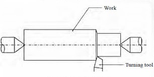
Turning in a lathe is to remove excess material from the work piece to produce a cylindrical surface of required shape and size. Straight turning The work is turned straight when it is made to rotate about the lathe axis and the tool is fed parallel to the lathe axis. The straight turning produces a cylindrical surface by removing excess metal from the work pieces.
Step turning
Step turning is the process of turning different surfaces having different diameters. The work is held between centres and the tool is moved parallel to the axis of the lathe. It is also called shoulder turning.
Chamfering
Chamfering is the operation of bevelling the extreme end of the work piece. The form tool used for taper turning may be used for this purpose. Chamfering is an essential operation after thread cutting so that the nut may pass freely on the threaded work piece.
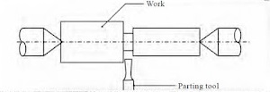
Grooving
Grooving is the process of cutting a narrow groove on the cylindrical surface of the work piece. It is often done at end of a thread or adjacent to a shoulder to leave a small margin. The groove may be square, radial or beveled in shape.
Undercutting
Undercutting is done (i) at the end of a hole (ii) near the shoulder of stepped cylindrical surfaces (iii) at the end of the threaded portion in bolts. It is a process of enlarging the diameter if done internally and reducing the diameter if done externally over a short length. It is useful mainly to make fits perfect. Boring tools and parting tools are used for this operation.
Forming
Forming is a process of turning a convex, concave or any irregular shape. For turning a small length formed surface, a forming tool having cutting edges conforming to the shape required is fed straight into the work.
Knurling
Knurling is the process of embossing a diamond shaped pattern on the surface of the work piece. The knurling tool holder has one or two hardened steel rollers with edges of required pattern. The tool holder is pressed against the rotating work. The rollers emboss the required pattern. The tool holder is fed automatically to the required length. Knurls are available in coarse, medium and fine pitches. The patterns may be straight, inclined or diamond shaped. The purpose of knurling is
1. To provide an effective gripping surface
2. To provide better appearance to the work
3. To slightly increase the diameter of the work
OR
IV. Explain the upright type drilling machine
The upright drilling machine is designed for handling medium sized work pieces. Though it looks like a sensitive drilling machine, it is larger and heavier than a sensitive drilling machine. Holes of diameter up to 50 mm can be made with this type of machine. It is also supplied with power feed arrangement. For drilling different types of work, the machine is provided with a number of spindle speeds and feed.
V. Illustrate the process of taper turning using compound rest method
The compound rest of the lathe is attached to a circular base graduated in degrees, which may be swivelled and clamped at any desired angle. The angle of taper is calculated using the formula: where D = Larger diameter d = Smaller diameter l = Length of the taper Ɵ = Half taper angle The compound rest is swiveled to the angle calculated as above and clamped. Feed is given to the compound slide to generate the required taper.
OR
VI. Sketch and explain the operations such as reaming, boring, counter sinking
Reaming
Reaming is a post drilling operation. It is an accurate way of sizing and finishing a hole which has been previously drilled. The tool used for reaming is known as reamer. The figure illustrates the reaming operation
Boring
1. To enlarge a hole by means of an adjustable single point cutting tool.
2. To finish a hole accurately and bring it to the required size.
3. To correct out of roundness of the hole.
4. To correct the location of the hole.
Boring is a post drilling operation performed for the following purposes
The figure illustrates the boring operation.
Countersinking
This is the operation of making a cone shaped enlargement at the end of the hole to provide recess for countersunk screw or rivet. The tool used is called a Countersink. The figure illustrates the countersinking operation.

VII. Illustrate the parts of a vertical milling machine
The principal parts of a vertical milling machine are shown in figure.
OR
VIII. Illustrate the parts of a horizontal milling machine
The principal parts of a horizontal milling machine are shown in figure.
IX. Explain the crank and slotted link mechanism used in shaper
The rotary movement o the main drive is converted into reciprocating movement of the ram by the mechanism contained within the column. Two different mechanisms used in mechanical shapers are:
1. Crank and slotted link mechanism
2. Whithworth mechanism
Crank and slotted link mechanism
1.Pinion 2.Ram 3.Ram positioning lead screw 4.Ram lock lever 5.Ram positioning hand wheel 6-7- Bevel gears 8.Fork 9.Slotted link 10.Sliding block 111.Pivot 12.Sliding block 2 13.Rotary slide lead screw 14.Bull gear 15.Pivot 16.Rotary slide 17-18-Bevel gears
Figure illustrates the crank and slotted link mechanism. The drive from the motor is transmitted to the bull gear through a gear box. The front face of the bull gear is fitted with a rotary slide. The slotted link which is also known as rocker arm is pivoted at the machine base. The upper end of the rocker arm is forked and connected to the ram. The sliding block of the rotary slide is fitted to move inside the slotted link. As the bull gear rotates, the ram connected to the rocker arm will reciprocate.
X. Sketch and explain the work holding devices used in slotter
The workpieces can be clamped on a slotter table in different ways.
1. Directly clamp on the table
2. Vice
3. Angle Plate
4. V-Block
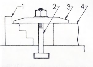
Direct Clamping
The workpieces can be clamped directly on the surface of the table by using T-bolt and nut as shown in figure.
1. Step block 2. T- bolt 3. Clamp 4. Work piece
Vice
This is the most generally used method for holding work pieces in slotter but limited to small width jobs which can be accommodated between the jaws. Parallel plates are used to support small thickness work piece.
Angle Plate
For machining a surface perpendicular to another surface, angle plates are used for clamping.
V-block
For machining on work pieces with round sections V-blocks are used for clamping.
1. T-bolt 2. V-block 3. Round work 4. Nut 5. Clamp
XI. Illustrate the working of honing operation
Honing is grinding or abrading process mostly for finishing round holes by means of bonded abrasive stones, called Honing tool shown in figure.
OR
XII. Identify the grinding wheel 51 A 36 L 5 V 23
The Indian standard marking system for grinding wheels has been prepared with a view of establishing a uniform system of marking of grinding wheels to designate its various charecteristics.
The grinding wheel designated as 51 A 36 L 5 V 23 represents its characteristic as:
51- Manufacturer's Prefix
A- Type of Abrasive ( Aluminium Oxide )
36- Grain Size - Medium
L- Grade - Medium
5- Structure- Dense
V- Type of Bond- Vitrified bond
23- Manufacturer's number- suffix
XIII. Discuss the machine set up Tool Cutter machine
Tool and cutter grinder are used mainly to sharpen and recondition multiple tooth cutters like reamers, milling cutters, drills, taps, hobs etc.
When a fluted tooth is being ground it is supported on a tooth rest whilst wheel passes over its edge. The tooth rest can be mounted either on the machine table or on the wheel head, depending on the cutter to be sharpened.
OR
XIV. Explain the principle of cylindrical type grinding machine